
Integrated Engineering System Structure
Connecting what a system must do, what it consists of, and how it is realized.
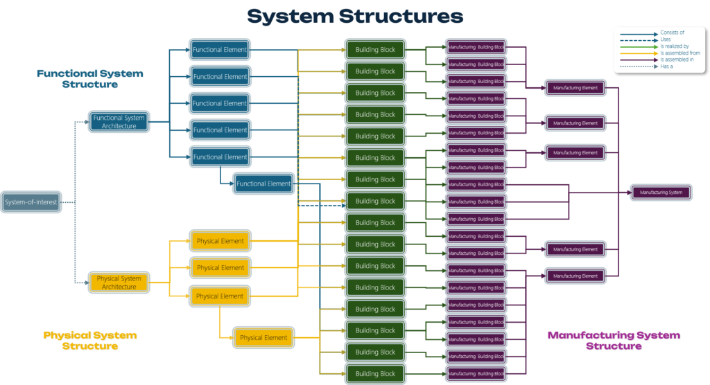
The complete System Structures view shows how the Functional System Structure, the Physical System Structure, the shared Building Blocks, and the Manufacturing System Structure relate to one another. Together, they provide an integrated view from system definition through to manufacturing realization.
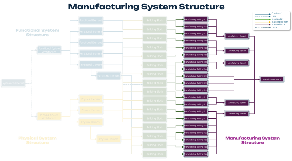
The Manufacturing System Structure belongs to the Manufacturing and Logistics domain. It starts from the Building Blocks defined by Engineering and describes how these are realized, assembled, and organized into Manufacturing Building Blocks, Manufacturing Elements, and ultimately the Manufacturing System.
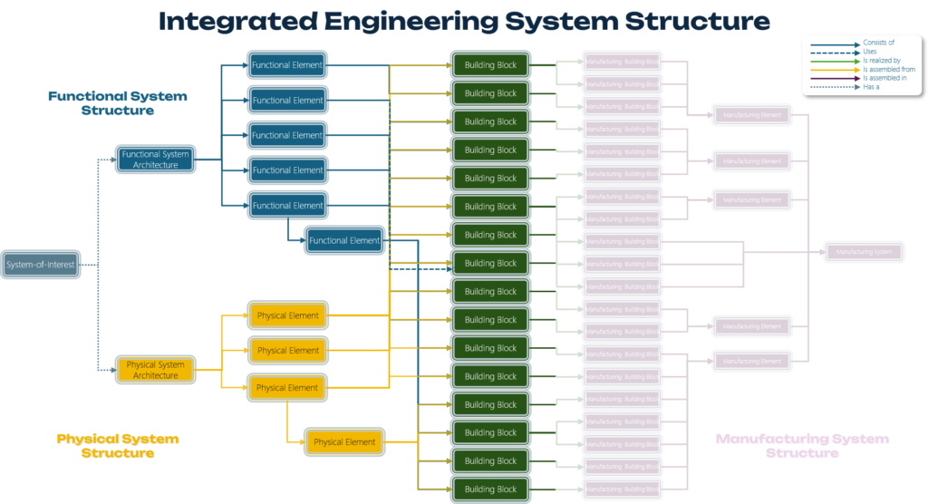
The Integrated Engineering System Structure (IESS) covers the Engineering domain. It consists of the Functional System Structure, the Physical System Structure, and the shared Building Block configuration. Together, these provide the complete engineering definition and specification of the System-of-Interest.
Understanding the IESS
The IESS describes the same System-of-Interest through two complementary structures: a Functional System Structure and a Physical System Structure. These structures answer different questions and therefore do not need to have the same decomposition.
What connects them is the system’s Building Block configuration. The Functional System Structure determines which Building Blocks are needed to fulfil the system’s functions, while the Physical System Structure determines where those same Building Blocks are positioned, mounted or assembled in the physical system.
Two different structures. One System-of-Interest. One complete Building Block configuration.
A simple analogy: preparing a meal
A simple way to understand the principle is to think about preparing a meal. Imagine that the menu describes what is to be served. Each dish has a purpose within that menu and requires a number of ingredients.
The combined shopping list identifies everything that is needed to realize the complete menu. Flour may be required for one dish, tomatoes for another, while some ingredients may even contribute to several dishes.
Once prepared, those same ingredients appear in a completely different organization: they are combined and positioned within starters, sauces, side dishes and main courses. Nothing required by the menu should mysteriously disappear, and nothing appearing on the plate should be there without a reason.
What must be provided?
What is needed to realize it?
Where does everything physically end up?
From the analogy to a real system: a passenger car
Now consider a passenger car as the System-of-Interest. One of the functions that the car must perform is to Control Vehicle Deceleration. This function can be represented by a Functional Element in the Functional System Structure.
Realizing this function requires several Building Blocks. Depending on the vehicle architecture, these may include a brake pedal, brake booster, hydraulic control unit, brake lines, brake calipers, brake discs and various sensors and electronic components.
From a functional perspective these Building Blocks belong together because they contribute to the same functional purpose. Physically, however, they are distributed throughout the vehicle. The brake pedal is located in the cabin, control equipment may be located elsewhere in the vehicle, brake lines run through the body or chassis, and brake calipers and discs are mounted at the wheel assemblies.
Functional completeness must become physical completeness.
If the functional definition of the passenger car is complete, all Building Blocks required to fulfil its functions must be identified. For the engineering definition of the car to be physically complete, every one of those Building Blocks must also have a place in the Physical System Structure.
The functional and physical structures may therefore look completely different, but they must ultimately account for the same complete system configuration.
Every Building Block has two places in the system
Within the IESS, a Building Block can therefore be viewed from two complementary perspectives. It has a functional parent, identifying the Functional Element to which it contributes, and a physical parent, identifying the Physical Element in which it is positioned, mounted or assembled.
A brake disc, for example, may contribute functionally to Control Vehicle Deceleration, while physically it is part of a Wheel Assembly. The Building Block itself does not have to be duplicated: the same engineering element participates in both structures through different relationships.
Functional parent Building Block Physical parent
The IESS thereby brings several concepts from the IMPULS3 Information Model together. Elements provide identity, Distinctions define what kind of element something is, Relationships capture its semantic connections, Structures organize those relationships into meaningful views, and Systems define which configuration of elements together constitutes the System-of-Interest.
In this way, the IESS provides a concrete application of the generic IMPULS3 Information Model: the information model defines how engineering information can be represented, while the IESS applies these concepts to define how the engineered system itself is structured.
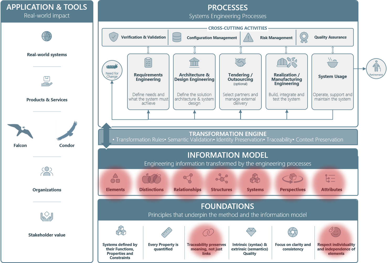
The IESS applies the concepts of the IMPULS3 Information Model to the structural definition of the System-of-Interest.
 References